We will see step-by-step how to use and implement the potentiometers from the Gamebuino accessory pack
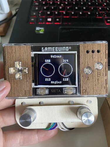
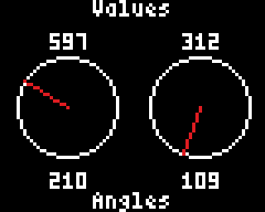
The goal is to produce a program looking like this :
For this we will need :
- A Gamebuino META console
- 2 Arduino compatible potentiometers (you can use a single one but it won’t look as cool)
- A computer with the Arduino IDE installed and configured
If you haven’t done it yet, please refer to the following guide to install and configure the Arduino IDE.
Get started (C++ 1/5) : Quick software setup - Gamebuino
If you already have solid knowledge in coding (or just don’t feel like going through this amazing tutorial) you can simply get the commented code from the Mini-code : potentiomètres (subject is in french but comments are in english)
Wiring
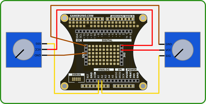
Before coding we need to plug the potentiometers to the console, preferably with the accessory backpack.
Note that the left potentiometer will use the A1 port while the right one will use the A2 port.
| Potentiomètre | Backpack | Couleur | Description |
|---|---|---|---|
| GND | GND | BROWN | Ground |
| VCC | 3V3 | RED | Power input |
| SIG | A1/A2 | YELLOW | Signal output |
Step 1 : easy start
First thing first, open the preconfigured Arduino IDE for Gamebuino
- You should see the following on your screen :
void setup() {
  // put your setup code here, to run once:
}

void loop() {
  // put your main code here, to run repeatedly:
}
This seems a little empty for now, we’re going to fill it up.
*Before anything else we need to add the following line at the start of our file :
#include <Gamebuino-Meta.h>
This is called a “library”, it will allow us to use a whole bunch of functions without the need to manually code them. This specific library contains all the Gamebuino functions and will be very useful for what’s coming next.
We need to add two functions to make our program work :
- In the setup() function we make a call to the gb.begin() function as follows :
void setup() {
  // put your setup code here, to run once:
  gb.begin();
}
The gb.begin() function initializes the console : without it nothing will work !
- Then we add the gb.waitForUpdate function in our main loop() function :
void loop() {
  // put your main code here, to run repeatedly:
  gb.waitForUpdate();
}
The gb.waitForUpdate() function allows for screen content refreshing (drawing things on it), handles sounds, buttons presses, in short everything needed for the console to come to life.
We now have a functionnal program structure, although it does nothing at the moment.
Plugging things in
Before laying down some code we need to plug in our potentiometers, preferably with the developper backpack.
Power inputs (VCC) go into 3v3 ports, ground pins (GND) go to, well, ground ports, and signal pins (SIG) go to analog ports A1 for the left potentiometer ans A2 for the right one.
Step 2 : Reading measurements and transforming them
Our potentiometers send analogic values, physical measurements, to our console. We will gather those measurements’ values and transform them into something the machine can understand, in this case a numerical value.
For this we will use the analogRead() function from the standard Arduino library. This function allows the transformation of an analogic (physical) value into a numerical value thanks to the ADC (Analog to Digital Converter) module of the console’s processor.
- We start by declaring two pairs of int32 type variables in which we’ll store our values and transform them :
int32_t i32_L_pot_value; //variables for the left potentiometer
int32_t i32_L_pot_angle;

int32_t i32_R_pot_value; //variables for the right potentiometer
int32_t i32_R_pot_angle;
Those declarations are made at the beginning of our code, between libraries inclusions and the setup() function.
Those variables declared outside a specific function are called “global” variables, they can be used and modified from about any point in our progra. In a small program like this one this is not an issue, but in a larger program with hundreds of lines of code and lots of variables this can be considered a bad habit to use too much global variables. This is because using too much of those can make following what part does what very tedious.
We will now declare a function to assign values to those new variables and transform them.
- This function will be called read_and_calc() since it will read values and perform calculations :
void read_and_calc() {

}
- We can add a call to this function in our main loop() function right away :
void loop() {
  // put your main code here, to run repeatedly:
  gb.waitForUpdate();

  read_and_calc();
}
Indeed, we want this function to be executed repeatedly in each loop of our program.
Now we need to fill up this function se it can do its job reading values thanks to the analogRead() function.
- The reading is done as such :
void read_and_calc() {
  i32_L_pot_value = analogRead(A1);
  i32_R_pot_value = analogRead(A2);
}
We assign our two variables the values read from our potentiometers continuously.
Those values are comprised between 0 and 1023, it’s good to keep this in mind but not particularly practical. Thus we will change those values to be comprised between 0 and 360 to represent angles, which are easier to picture and understand.
- This change is done simply by applying a small mathematical formula :
void  read_and_calc(){

  i32_L_pot_value = analogRead(A1);
  i32_R_pot_value = analogRead(A2);

  // we convert the values from a range of 0 to 1023 to angles within 360 degrees
  i32_L_pot_angle = (i32_L_pot_value * 360) / 1023;
  i32_R_pot_angle = (i32_R_pot_value * 360) / 1023;
}
With a basic cross-product we tweaked our values from a 0 to 1023 range to “angles” values between 0 and 360.
Step 3 : Displaying values
To better represent the action of our potentiometers we will display the values we got at the previous step on the screen to monitor them.
For this we will use a dedicated display function that we’ll call draw_interface()
*We declare this function in our scope as follows :
void  draw_interface(){
  // the clear function is needed to reset the screen between each frame, otherwise frames would mix together and get messy
  gb.display.clear();
}
Note that we need the clear() function to avoid frames “piling up” and becoming unreadable.
- Of course we add a call to our new function within our main loop() function so it’s called on each cycle :
void loop() {
  // put your main code here, to run repeatedly:
  gb.waitForUpdate();

  // the read_and_calc function will handle the data acquisition and math needed for the program
  read_and_calc();

  //the draw_interface function will handle the display of a custom interface
  draw_interface();
}
Our loop() function is new complete, we won’t be adding new elements inside, the modifications will now take place directly withing the read_and_calc() and/or draw_interface() functions.
Now we have to complete our draw_interface function to display our raw values and our angle values.
- Nothing too hard with the printf function included in our Gamebuino :
void  draw_interface(){
  // the clear function is needed to reset the screen between each frame, otherwise frames would mix together and get messy
  gb.display.clear();

  gb.display.printf(" L_value = %d\n L_angle = %d\n R_value = %d\n R_angle = %d", i32_L_pot_value, i32_L_pot_angle, i32_R_pot_value, i32_R_pot_angle);
}
It may seem heavy but it is simply the formating of text needed by the function. Le text between quotes is displayed as is, the %d are values to be fetched from the variables specified after quotes, separated by commas, and the \n are newlines.
(The printf function is a standard C function, if you want a good headache go read its full documentation or its source code).
By launching the compilation of your code and uploading it to your console you should see the following appear on your screen :
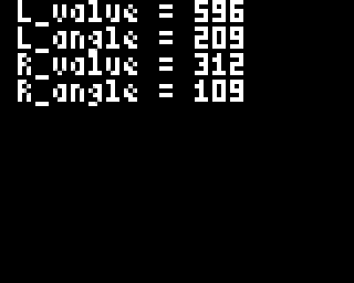
That’s a start, but it’s quite bland and frankly a bit ugly. So we will now improve it.
Step 4 : Adding visuals
In this part we will see how to transform the values we got earlier into two identical visual representations, as seen on the picture at the beginning of this tutorial.
For this we will use some mathematical formulas, namely sin() and cos(). (in case you studied math in high school you should be ok, otherwise brace yourselves).
But before that we will use defines to establish the dimensions and positions of two circles that will act as the basis of our visuals.
- Those defines are placed at the beginning of our program, right below our library inclusions :
//define of our circles' properties, here the radius is 15 units and both are centered on the screen
#define CIRCLE_R 15
#define L_CIRCLE_X (gb.display.width()/4)
#define R_CIRCLE_X ((gb.display.width()/4)*3)
#define CIRCLE_Y (gb.display.height()/2)
This way we determine a radius (CIRCLE_R) of 15 units, a horizontal position (CIRCLE_X) at 1/4th of the screen for the left circle and 3/4th for the right one, the two circles will be vertically centered (CIRCLE_Y).
We can now do two additional things :
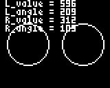
- Display our circles on the screen :
void  draw_interface(){
  // the clear function is needed to reset the screen between each frame, otherwise frames would mix together and get messy
  gb.display.clear();

  gb.printf(" L_value = %d\n L_angle = %d\n R_value = %d\n R_angle = %d", i32_L_pot_value, i32_L_pot_angle, i32_R_pot_value, i32_R_pot_angle);

  // we draw the circles with the properties we defined at the beginning, their centers' positions and radius
  gb.display.drawCircle(L_CIRCLE_X, CIRCLE_Y, CIRCLE_R);
  gb.display.drawCircle(R_CIRCLE_X, CIRCLE_Y, CIRCLE_R);
}
- Hide the text we displayed before by turning the printf() call into a commentary :
void  draw_interface(){
  // the clear function is needed to reset the screen between each frame, otherwise frames would mix together and get messy
  gb.display.clear();

//  gb.printf(" L_value = %d\n L_angle = %d\n R_value = %d\n R_angle = %d", i32_L_pot_value, i32_L_pot_angle, i32_R_pot_value, i32_R_pot_angle);

  // we draw the circles with the properties we defined at the beginning, their centers' positions and radius
  gb.display.drawCircle(L_CIRCLE_X, CIRCLE_Y, CIRCLE_R);
  gb.display.drawCircle(R_CIRCLE_X, CIRCLE_Y, CIRCLE_R);
}
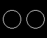
Beware ! Here come the calculations using sin() and cos() to add “clock hands” within our circles that will move according to the position of our potentiometers.
For that we will declare two pairs of global variables that we will use to place points on the perimeter of each circle, so we can then trace lines between the center of the circles and the exterior points to represent our “hands”.
- Those declarations are made like this, always at the beginning of our program :
//variable declaration for the points used to draw lines
int16_t i16_L_point_x;
int16_t i16_L_point_y;

int16_t i16_R_point_x;
int16_t i16_R_point_y;
We now have a pair of variables for each point, we will use them as X and Y coordinates to determine their positions in space.
Now we need to assign values to those variables so they make themselves useful.
We need to add the “math.h” library to our program.
- This is done simply by including the library at the top of our program, just below the Gamebuino library :
#include <Gamebuino-Meta.h>
//we include the math library to get access to sin() and cos() functions as well as a value of PI used in the program
#include <math.h>
It gives us access to a predetermined PI value within the library as well as the sin() and cos() functions. It is possible to not include this math.h library since sin() and cos() are supposed to be included in the Arduino library by default along a macro that gives a rounded PI value, we iinclude it nonetheless for the principle of it.
- To assign values to our variables we use the following formulas withing our read_and_calc() function :
  // we calculate the coordinates of a point on a circular perimeter corresponding to the value of the angle found above
  // note the multiplication by PI/180, this is because the angle we calculated in degrees must be converted to radians
  i16_L_point_x = L_CIRCLE_X + CIRCLE_R * cos(i32_L_pot_angle * M_PI/180);
  i16_L_point_y = CIRCLE_Y + CIRCLE_R * sin(i32_L_pot_angle * M_PI/180);

  i16_R_point_x = R_CIRCLE_X + CIRCLE_R * cos(i32_R_pot_angle * M_PI/180);
  i16_R_point_y = CIRCLE_Y + CIRCLE_R * sin(i32_R_pot_angle * M_PI/180);
This determines dynamically the position of the points on the perimeter of our circles depending on the reading values we transformed into angles.
Once those coordinates are determined we can use them to trace our “hands” within our circles.
- This is performed by the drawLine() function called in our draw_interface() function as follows :
  // we draw the circles with the properties we defined at the beginning, their centers' positions and radius
  gb.display.drawCircle(L_CIRCLE_X, CIRCLE_Y, CIRCLE_R);
  gb.display.drawCircle(R_CIRCLE_X, CIRCLE_Y, CIRCLE_R);
  // we draw a line between the center of the circle and the point on its perimeter corresponding to the potentiometer value we read
  gb.display.setColor(RED);
  gb.display.drawLine(L_CIRCLE_X, CIRCLE_Y, i16_L_point_x, i16_L_point_y);
  gb.display.drawLine(R_CIRCLE_X, CIRCLE_Y, i16_R_point_x, i16_R_point_y);
We add the setColor(RED) function so our “hands” are red, it looks nicer. If you’re allergic to red you can pick another color such as GREEN or BLUE for instance, beware of fashion faux-pas though.
Launch the compilation and uploading of your code and you should get the following result :
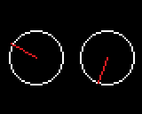
Just one more step and we will have the exact same program as on the picture shown at the start.
Step 5 : Move the text
We will cut the text we had previously into several parts so the different elementss can be dispatched all over the screen.
For this we will mainly use the setCursor function that allows us to freely move the text cursor around the screen with X and Y coordinates. Along with the printf() function it gives up the possibility to put text exactly where we want it without the need to format a really long and convoluted string of text made mainly of blankspaces and newlines.
Everything takes place in our draw_interface() function of course.
- We start by placing the words “values” and “angles” in the middle of the screen, respectively at the top and at the bottom :
void  draw_interface(){
  // the clear function is needed to reset the screen between each frame, otherwise frames would mix together and get messy
  gb.display.clear();

  // we print the value read from the potentiometer and its value when converted to an angle
  gb.display.setCursor(gb.display.width()/2 - 12, 0);
  gb.display.printf("Values");
  gb.display.setCursor(gb.display.width()/2 - 12, gb.display.height() - 6);
  gb.display.printf("Angles");

//...
}
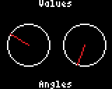
- We continue with raw values positioned above our circular frames :
void  draw_interface(){

//...

  //raw values display
  gb.display.setCursor(gb.display.width()/4 - 5, CIRCLE_Y - CIRCLE_R - 7);
    gb.display.printf("%d", i32_L_pot_value);

  gb.display.setCursor((gb.display.width()/4)*3 - 5, CIRCLE_Y - CIRCLE_R - 7);
    gb.display.printf("%d", i32_R_pot_value);

//...
}
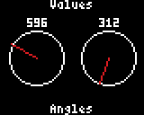
- We finish with angle values calculated earlier tat we place under the frames :
void  draw_interface(){

//...

  //angles' values display
  gb.display.setCursor(gb.display.width()/4 - 5, CIRCLE_Y + CIRCLE_R + 5);
    gb.display.printf("%d", i32_L_pot_angle);

  gb.display.setCursor((gb.display.width()/4)*3 - 5, CIRCLE_Y + CIRCLE_R + 5);
    gb.display.printf("%d", i32_R_pot_angle);

//...
}
And voilà !
You survived through this new tutorial, congrats ! You now have a nice little program you made with your own hands to test you potentiometers. Your turn now.
