Welcome to this step-by-step tutorial on how to implement a joystick on your Gamebuino Meta.
This tutorial is intended for the hardware provided in the Gamebuino accessory pack

You will need :
- a Gamebuino META
- an Arduino compatible joystick
- a computer with the Arduino IDE installed
If you haven’t done it yet, please refer to the following page to install and configure the Arduino IDE :
Get started (C++ 1/5) : Quick software setup - Gamebuino
If you already know how to code or just don’t feel like going through the whole tutorial you can fin the commented code of the program we present here on the Mini-code : joystick
Wiring :
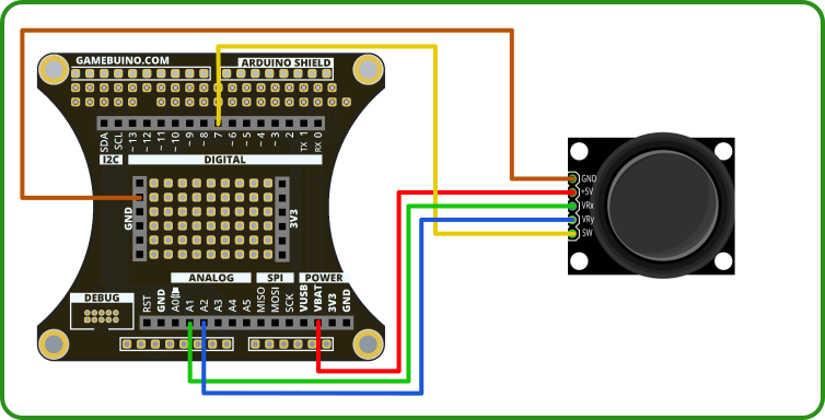
| Joystick | Backpack | Couleur | Description |
|---|---|---|---|
| GND | GND | BROWN | Ground |
| 5V | VBAT | RED | Power input |
| VRX | A1 | GREEN | X Axis |
| VRY | A2 | BLUE | Y Axis |
| SW | 7 | YELLOW | Click switch |
Step 1 : easy start
First thing first, open the preconfigured Arduino IDE for Gamebuino
- You should see the following on your screen :
void setup() {
  // put your setup code here, to run once:
}

void loop() {
  // put your main code here, to run repeatedly:
}
This seems a little empty for now, we’re going to fill it up.
*Before anything else we need to add the following line at the start of our file :
#include <Gamebuino-Meta.h>
This is called a “library”, it will allow us to use a whole bunch of functions without the need to manually code them. This specific library contains all the Gamebuino functions and will be very useful for what’s coming next.
We need to add two functions to make our program work :
- In the setup() function we make a call to the gb.begin() function as follows :
void setup() {
  // put your setup code here, to run once:
  gb.begin();
}
The gb.begin() function initializes the console : without it nothing will work !
- Then we add the gb.waitForUpdate function in our main loop() function :
void loop() {
  // put your main code here, to run repeatedly:
  gb.waitForUpdate();
}
The gb.waitForUpdate() function allows for screen content refreshing (drawing things on it), handles sounds, buttons presses, in short everything needed for the console to come to life.
We now have a functionnal program structure, although it does nothing at the moment.
Step 2 : read data from the joystick
In this step we’ll see how to gather the data sent by the joystick to integrate those in our program.
For this we will use two functions :
- the analogRead() function that allows to read a value from an analogic port
- the digitalRead() function that allows to read a value from a digital port
- those names are rather explicit, good, this will not always be the case for standard functions
Before reading the values we will use a very useful feature of C++ : the define.
A define allows one the integrate “keywords” in their code by creating associations of terms. Here we will use defines to make the differenciation between the three inputs used by our joystick easier.
- We proceed in the following way :
#define JOY_X_AXIS A1
#define JOY_Y_AXIS A2
#define JOY_SWITCH 7
It is much easier to get around using defines because we can be very descriptive. Here the use of defines is a bit superfluous since we only have 3 elements to differentiate. But imagine how tedious it would be for 10, 20, or more elements. Defines are good, eat some.
By convention defines are places at the beginning of a program, I encourage you to play around to understand exactly why ;p
Now that our entry pins are well defined we can proceed to read the values without further issues.
- To do that we use our reading functions :
void loop(){
  // put your main code here, to run repeatedly:
  gb.waitForUpdate();

 int32_t i32_stick_x_value = analogRead(JOY_X_AXIS);
 int32_t i32_stick_y_value = analogRead(JOY_Y_AXIS);
 int32_t i32_joy_switch_value = digitalRead(JOY_SWITCH);
}
We store the values sent by our joystick in 3 different variables directly inside our loop() function. This mehod is not perfect but our program being very light we don’t have to optimize everything.
Step 3 : Display reading values
Now that we were able to gather the data from our joystick we will display it on screen. It allows to check the condition of the stick and to understand how it works, which will be useful later.
To display our values we will create a dedicated function for this task.
- we declare the function as follows :
void joystick_display( int32_t X_value, int32_t Y_value, int32_t SWITCH_value){

  gb.display.clear();
}
The function gb.display.clear() is used to clear the screen between each frame, otherwise images would “pile up” and quickly become messy.
Note the variables indicated between parentheses after our function name : they are parameters, values we will “pass on” to our function so it can use them.
Turns out we will use those right away, rest assured it is quite simple. We will use the gb.display.printf function to display our values on screen along with a bit of text to make it more comprehensible.
- for this we simply add a call to the printf function such as :
void joystick_display( int32_t X_value, int32_t Y_value, int32_t SWITCH_value){

  gb.display.clear();

 gb.display.printf(" X_axis = %d\n Y_axis = %d\n switch = %d", X_value, Y_value, SWITCH_value);
}
It may seem a bit convoluted but it is in fact very straightforward : the text between quotes in the message to be printed, the “%d” are numerical values corresponding to the variables specified in order and separated by commas, lastly the \n are newlines to split our text on 3 lines.
Nothing really complicated in the end. The benefit of using printf is to be able to display everyting with one function call where gb.display.print would require 6 separate ones.
- And of course we all a call to our value_display() function in our main loop() function and we give it the variables read previously as parameters :
void loop(){
  // put your main code here, to run repeatedly:
  gb.waitForUpdate();

 int32_t i32_stick_x_value = analogRead(JOY_X_AXIS);
 int32_t i32_stick_y_value = analogRead(JOY_Y_AXIS);
 int32_t i32_joy_switch_value = digitalRead(JOY_SWITCH);

 joystick_display(i32_stick_x_value, i32_stick_y_value, i32_joy_switch_value);
}
Use auto-check on your code and upload it to your console to see if eveything works properly, you should get the following to appear on screen :
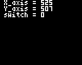
Move the stick around and click on it to see the values changing.
You should notice a small issue with the switch, the value seems to randomly flickers and not respond to actual clicks.
To fix it we need a small adjustment. Our switch pin isn’t analogic but digital, thus we need to configure this entry pin in a specific way for it to act the way we want. Don’t panic now, no need to code something complicated to achieve this (for now).
- We have to use the pinMode() function as such to fix our problem :
void setup() {
  // put your setup code here, to run once:
  gb.begin();

  //set the input mode of the switch pin to INPUT_PULLUP
  //using only the INPUT mode will make the value flicker constantly
  pinMode(JOY_SWITCH, INPUT_PULLUP);
}
The issue is fixed.
Step 4 : Add some visual
Up until now we were able to gather data from our joystick and display it on screen. It’s good but it is neither good-looking nor very easy to undertand. Thus we will add a visual transcription of what our joystick does.
To get started on this, would you have some more define ?
- We’ll define the dimensions of a circle that we will then use in our display :
#define CIRCLE_X (gb.display.width()/2)
#define CIRCLE_Y (gb.display.height()/2 + 8)
#define CIRCLE_RAD (gb.display.height()/3)
Remember that defines are placed at the top of a program
With those we can easily display a circle on screen. To do so we will use the gb.display.drawCircle() function into our joystick_display() function while giving it the dimensions specified with our defines.
*It works in the following way :
void joystick_display( int32_t X_value, int32_t Y_value, int32_t SWITCH_value){
gb.display.clear();
gb.display.printf(" X_axis = %d\n Y_axis = %d\n switch = %d", X_value, Y_value, SWITCH_value);
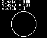
gb.display.drawCircle(CIRCLE_X, CIRCLE_Y, CIRCLE_RAD);
}
This will display an empty white circle on screen with the size and coordinates we gave it.
To repredent the movement of our joystick we will add a red dot that will move inside the circle depending on the values sent by the stick.
For this we will define the coordinates of the dot the dynamic way. Nothing too fancy here, that’s already what we’re doing for the reading of the stick values. We will simply adapt the code to define two variables instead of reading values.
- We simply declare two variables and assign them values with a small mathematic formula toreport them the values of our X and Y axis while staying inside the circle :
void joystick_display( int32_t X_value, int32_t Y_value, int32_t SWITCH_value){

  gb.display.clear();

 gb.display.printf(" X_axis = %d\n Y_axis = %d\n switch = %d", X_value, Y_value, SWITCH_value);

 gb.display.drawCircle(CIRCLE_X, CIRCLE_Y, CIRCLE_RAD);

 int32_t i32_x_dot = ((X_value - 512) * CIRCLE_RAD) / 1023;
 int32_t i32_y_dot = ((Y_value - 512) * CIRCLE_RAD) / 1023;
}
To display the dot we will use the gb.display.fillCircle() function that so happens to draw a full circle on screen.
- It looks something like this :
void joystick_display( int32_t X_value, int32_t Y_value, int32_t SWITCH_value){

  gb.display.clear();

 gb.display.printf(" X_axis = %d\n Y_axis = %d\n switch = %d", X_value, Y_value, SWITCH_value);

 gb.display.drawCircle(CIRCLE_X, CIRCLE_Y, CIRCLE_RAD);

 int32_t i32_x_dot = ((X_value - 512) * CIRCLE_RAD) / 1023;
 int32_t i32_y_dot = ((Y_value - 512) * CIRCLE_RAD) / 1023;
 gb.display.fillCircle(i32_x_dot + CIRCLE_X, i32_y_dot + CIRCLE_Y, 5);
}
Let’s add a bit of color shall we ?
It will only require a small line of code, thanks to the gb.display.setColor() that allows to … set a display color.
- We call this function right before our dot display :
void joystick_display( int32_t X_value, int32_t Y_value, int32_t SWITCH_value){
gb.display.clear();
gb.display.printf(" X_axis = %d\n Y_axis = %d\n switch = %d", X_value, Y_value, SWITCH_value);
gb.display.drawCircle(CIRCLE_X, CIRCLE_Y, CIRCLE_RAD);
int32_t i32_x_dot = ((X_value - 512) * CIRCLE_RAD) / 1023;
int32_t i32_y_dot = ((Y_value - 512) * CIRCLE_RAD) / 1023;
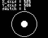
gb.display.setColor(RED);
gb.display.fillCircle(i32_x_dot + CIRCLE_X, i32_y_dot + CIRCLE_Y, 5);
}
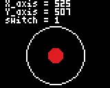
And voilà !
You now have a fully functionning program that will allow you to test your brand new joystick and check if it works properly.
The more observants will notice that the stick does not actually move in a circle but rather in a square, it’s normal. The circular movement we are used to is a mechanical effect which soed not exist for the digital machine. If we wanted a true circular movement we’d have to cheat a bit and extrapolate the reading values onto a circle pattern, at the moment this is outside my field of expertise, as such I won’t be taking you through such an ordeal, at least not for now.
You survived this tutorial, congrats ! See you soon for more adventures.