Voici le code commenté que j’ai écrit pour pouvoir utiliser simplement un joystick standard sur la Meta. Vous êtes libres d’utiliser ce code tel quel ou de le modifier à votre convenance pour ajouter des fonctionnalités.
Si vous souhaitez apprendre à réaliser ce programme vous-même ou n’arrivez pas à comprendre simplement en lisant le code commenté (ce qui n’est pas forcément évident quand on débute, on en passe tous par là) vous pouvez suivre notre fantastique tuto pas-à-pas : joystick pour Gamebuino Meta.
/*Code by Tom from Gamebuino
 * Version 1.0
 * 22 of april 2021
 *
 * Intended as a simple demonstration of hardware use on the Gamebuino Meta console
 * Feel free to reuse this code and implement your own functionnalities
 */

#include <Gamebuino-Meta.h>

//variable declaration for the stick axis values and switch value
int32_t i32_X_axis;
int32_t i32_Y_axis;
int32_t i32_click = 0;

//variables used to draw the stick position as a DOT
int32_t i32_x_dot;
int32_t i32_y_dot;


//define of the 2 analog pins for axis values and digital pin for switch
#define X_PIN A1
#define Y_PIN A2
#define SWITCH_PIN 7

//define the values used to draw a circle in which to show stick position as a DOT
#define CIRCLE_X (gb.display.width()/2)
#define CIRCLE_Y (gb.display.height()/2 + 5)
#define CIRCLE_RAD (gb.display.height()/3)

void setup() {
  // put your setup code here, to run once:
  gb.begin();

  //set the input mode of the switch pin to INPUT_PULLUP
  //using only the INPUT mode will make the value flicker constantly
  pinMode(SWITCH_PIN, INPUT_PULLUP);
}

void loop() {
  // put your main code here, to run repeatedly:
  while (!gb.update());

  // the logic function will handle the math needed for the program
  logic();

  //the draw function will handle the display of all the elements needed for the program
  draw();

}

void  logic(){
  //we read the values from the stick pins
  i32_X_axis = analogRead(X_PIN);
  i32_Y_axis = analogRead(Y_PIN);

  //we convert those values to coordinates within a circle to have a visual feedback with the DOT
  //we substract half the maximum value of the stick input
  //since the default position is roughly X = 512 and Y = 512 this allows for a default position of 0, 0 instead
  i32_x_dot = ((i32_X_axis - 512) * CIRCLE_RAD) / 1023;
  i32_y_dot = ((i32_Y_axis - 512) * CIRCLE_RAD) / 1023;

  //we read the switch pin value to determine wheter the switch is active or not
  //by default an idle switch reads as 1 and an active one reads as 0
  i32_click = digitalRead(SWITCH_PIN);
}

void  draw(){
  // the clear function is needed to reset the screen between each frame, otherwise frames would mix together and get messy
  gb.display.clear();

  //we display all the raw values we read from our input pins in order, which makes our setup easier to understand
  gb.display.print(" X axis = ");
  gb.display.print(i32_X_axis);
  gb.display.print("\n Y axis = ");
  gb.display.print(i32_Y_axis);
  gb.display.print("\n ");
  gb.display.print(i32_click);
  if(!digitalRead(SWITCH_PIN)){
     gb.display.print(" CLICK");
  }

  //we draw a static circle in which we add a dynamic red DOT to show the stick position in real time
  gb.display.drawCircle(CIRCLE_X, CIRCLE_Y, CIRCLE_RAD);
  gb.display.setColor(RED);
  gb.display.fillCircle(i32_x_dot + CIRCLE_X, i32_y_dot + CIRCLE_Y, 5);
}
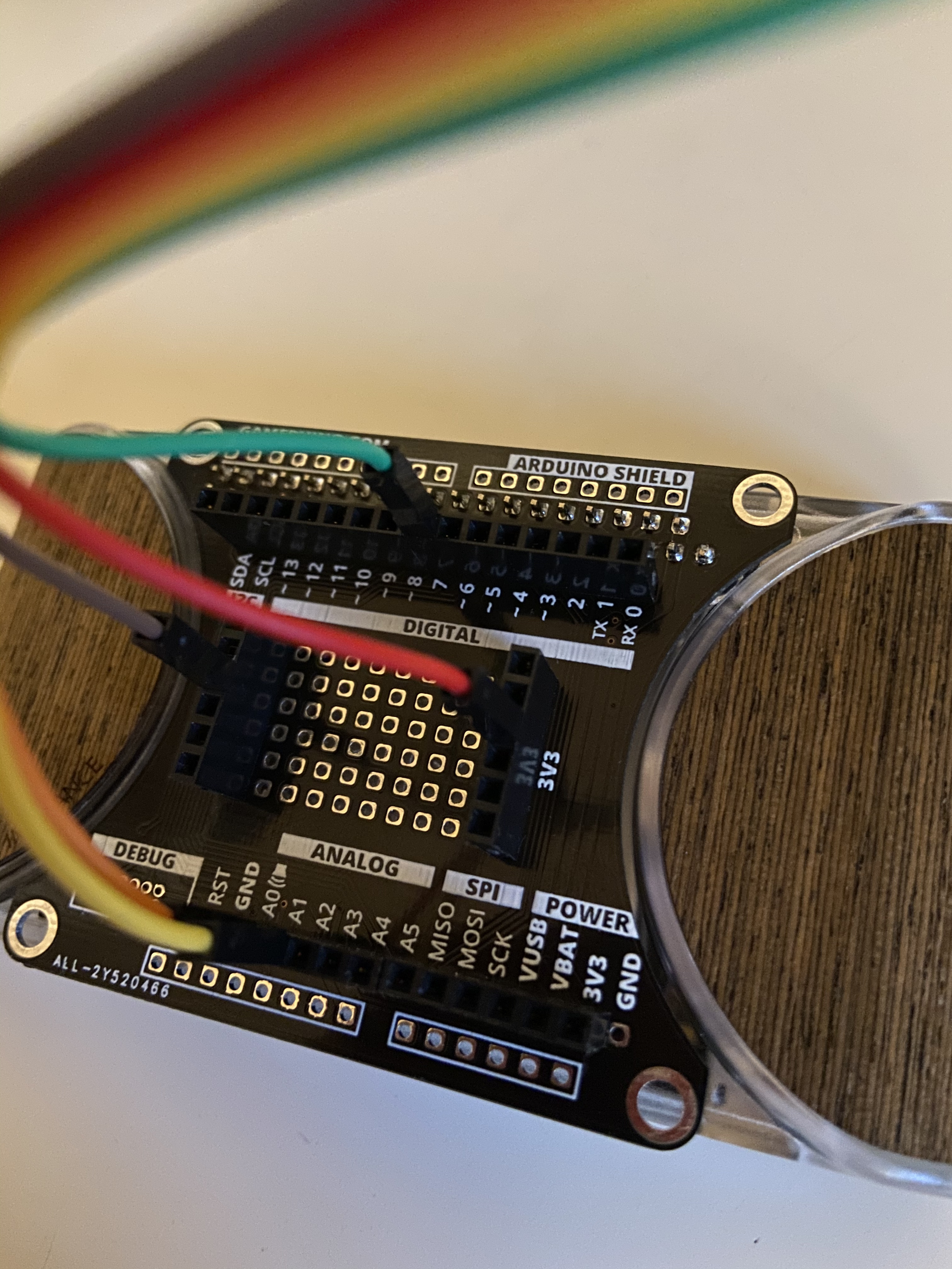
Et voici deux photos montrant le branchement du joystick à la console grâce à la carte d’extension developper backpack de Gamebuino :
Les sorties X et Y sont branchées sur les pins analogiques A1 et A2 respectivement, la sortie switch sur le pin digital 7 et l’alimentation et la masse sur des pins 3v3 et masse.