Here is a step-by-step tutorial that will help you to code a simple program to use an ultrasonic sensor with your console.
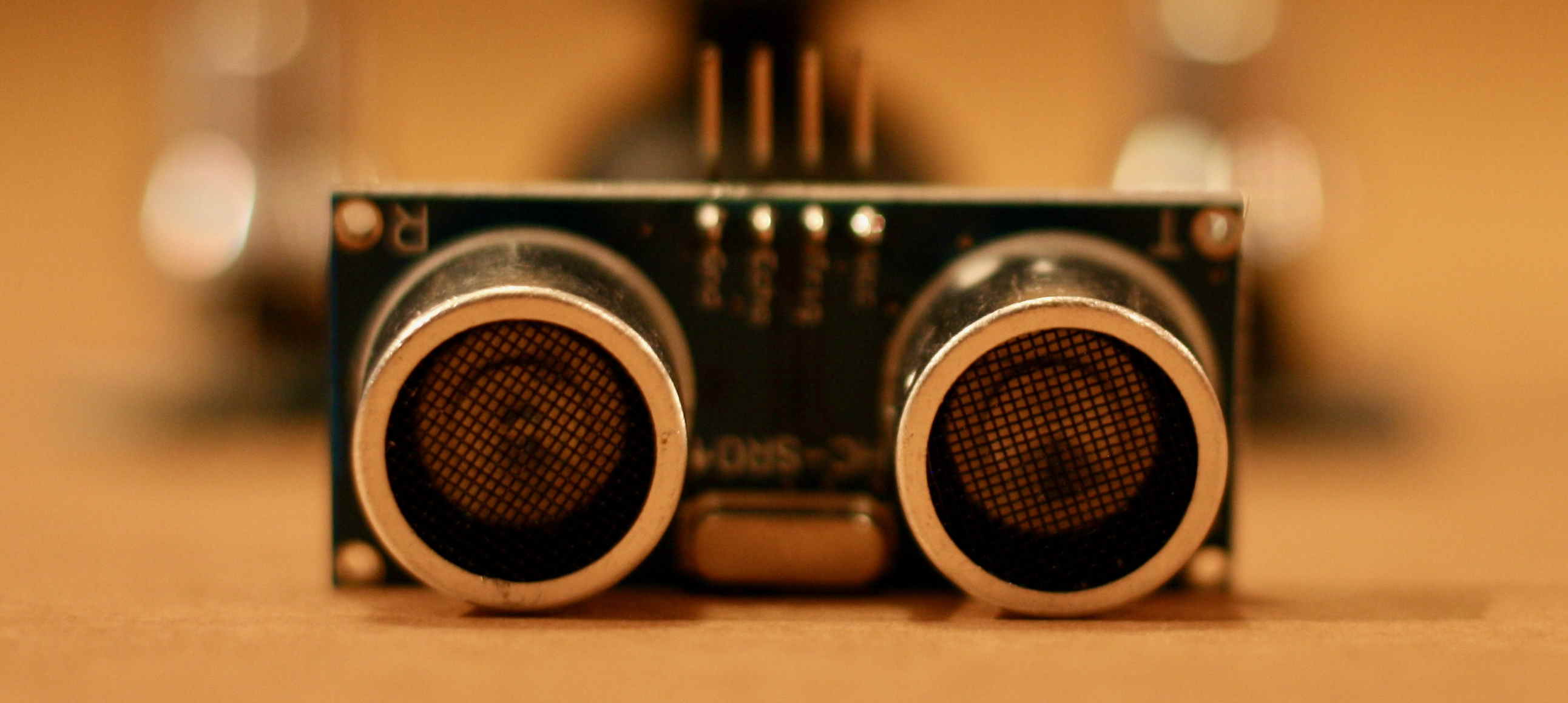
This tutorial is designed to be used with the hardware provided in the Gamebuino accessory pack. It does work with other Arduino compatible ultrasonic sensors though.
For this tutorial you will need :
- A Gamebuino META console
- an arduino compatible ultrasonic sensor
- A computer with the Arduino IDE installed
If you didn’t install it yet, please refer yourself to the following page for an easy setup of the IDE :
Get started (C++ 1/5) : Quick software setup - Gamebuino
The complete program made in this tutorial can be found in the Mini-code subject in case you don’t want to go through the whole thing.
Step 1 : Easy start
First thing first, open the preconfigured Arduino IDE for Gamebuino
- You should see the following on your screen :
void setup() {
  // put your setup code here, to run once:
}

void loop() {
  // put your main code here, to run repeatedly:
}
This seems a little empty for now, we’re going to fill it up.
*Before anything else we need to add the following line at the start of our file :
#include <Gamebuino-Meta.h>
This is called a “library”, it will allow us to use a whole bunch of functions without the need to manually code them. This specific library contains all the Gamebuino functions and will be very useful for what’s coming next.
We need to add two functions to make our program work :
- In the setup() function we make a call to the gb.begin() function as follows :
void setup() {
  // put your setup code here, to run once:
  gb.begin();
}
The gb.begin() function initializes the console : without it nothing will work !
- Then we add the gb.waitForUpdate function in our main loop() function :
void loop() {
  // put your main code here, to run repeatedly:
  gb.waitForUpdate();
}
The gb.waitForUpdate() function allows for screen content refreshing (drawing things on it), handles sounds, buttons presses, in short everything needed for the console to come to life.
We now have a functionnal program structure, although it does nothing at the moment.
Plugging things in
Before laying down some code we need to plug in the servomotor, preferably with the developper backpack.
Power input (VCC) goes into a 3V3 port, ground pin (GND) goes to, well, a ground port, while the TRIG and ECHO pins go to digitals ports, namely ECHO on D3 and TRIG on D3.
Step 2 : Read data from the sensor
Before getting a distance measurement with our sensor we need to gather rata from it, this requires a few setup steps to allow the sensor to communicate with the console.
- First we need to configure the input/output of our sensor within our program as follows :
#include <Gamebuino-Meta.h>

#define US_PIN_INPUT_ECHO   3   // Attache le pin D3 au pin Echo du capteur US
#define US_PIN_OUTPUT_TRIG  4   // Attache le pin D4 au pin Trig du capteur US
By using defines we give “names” to our D3 and D4 pins so we can differenciate them and reference them later in our program.
- We then need to configure the interaction mode of those pins in our setup() function :
void setup() {
  gb.begin();

  pinMode( US_PIN_OUTPUT_TRIG, OUTPUT);   // Définit le pin TRIG comme sortie (OUTPUT)
  pinMode( US_PIN_INPUT_ECHO, INPUT);     // Définit le pin ECHO comme entrée (INPUT)
  digitalWrite(US_PIN_OUTPUT_TRIG, LOW);  // Démarrage du pin TRIG en mode sortie faible
}
This is a crucial step, if we don’t define those pin modes properly it is impossible to communicate with the sensor.
Now we can proceed to data gathering and measurement.
For this we will declare a new function called ultrasonic_measure() with a float type return.
- Declaration is done this way :
float ultrasonic_measure() {

}
So far so good.
- Now we add the following lines to activate our TRIG ultrasonic emitter for 10ms :
float ultrasonic_measure() {

 digitalWrite(US_PIN_OUTPUT_TRIG, HIGH);
 delayMicroseconds(10);             // Activate TRIG pin as HIGH for 10 ms
 digitalWrite(US_PIN_OUTPUT_TRIG, LOW);
}
It allows us to send an ultrasonic wave which travel time will be measured with our ECHO pin.
- This specific measure is done as follows :
float ultrasonic_measure() {

  digitalWrite(US_PIN_OUTPUT_TRIG, HIGH);
  delayMicroseconds(10);                  // Activate TRIG pin as HIGH for 10 ms
  digitalWrite(US_PIN_OUTPUT_TRIG, LOW);

  long duration = pulseIn(US_PIN_INPUT_ECHO, HIGH, 20000);   // Reads the ECHO pin, returns ultrasound travel time in microseconds
  duration = duration * 144 / 100;  // Measure needs to be adjusted by 44% of the value sent by pulseIn()

  // Distance calculation
  long distance = duration * 0.034 / 2; // Speed of sound / 2 (because it goes back and forth)

  f32_distance = f32_distance*.9 + 0.1 * distance;
  return f32_distance;
}
We measure the gap between our TRIG pin activation and the detection of the soundwave by the ECHO pin. The value is adjusted by 44% and gives us the duration in microseconds. This adjustment is necessary due to the sensor itself. We can then divide this duration by half the speed of sound to get a distance, according to the formula D = T * S (half the speed because the wave goes back and forth and thus travels two times the distance).
At the end of the function we simply return our distance value.
And finally we call our ultrasonic_measure() function within our loop()
- We seize this opportunity to pad our value such as :
void loop() {
  gb.waitForUpdate();

  float d = ultrasonic_measure();
  if ( d > 50 ) d = 50;
  if ( d < 5 ) d = 5;
}
This way we only measure between 5 and 50 cm. Of course you can adjust this padding if you want. The sensor is precise up to 3-4 meters.
Step 3 : Adding a visual
In this part we will display the values obtained previsouly and transform them into a dynamic gauge to represent distance.
- We begin by declaring a display_bar(float) function that we then call into our loop() :
void  display_bar(float distance) {

  gb.display.clear();
}
void loop() {
  gb.waitForUpdate();

  float d = ultrasonic_measure();
  if ( d > 50 ) d = 50;
  if ( d < 5 ) d = 5;

  display_bar(d);
}
Here the function simply takes a float as parameter and only clears the screen on each cycle.
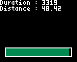
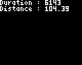
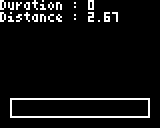
- We then add the display of our time and distance values :
void  display_bar(float distance) {

  gb.display.clear();

  gb.display.print( "Duration : ");
  gb.display.println(duration);

  gb.display.print( "Distance : ");
  gb.display.println(f32_distance);
}
Nothing too complicated, we simply use standard display functions to add text and numerical values.
We can now create our distance gauge.
- First we display an empty rectangle using the drawRect() function :
void  display_bar(float distance) {

  gb.display.clear();

  // Values display

  // Gauge display
  gb.display.drawRect(5, gb.display.height() - 15, gb.display.width() - 10, 10);
}
- Then we fill this gauge using the fillRect() function, AND we adjust the filling color depending on the distance :
void  display_bar(float distance) {

  gb.display.clear();

  // Values display

  // Gauge display
  gb.display.drawRect(5, gb.display.height() - 15, gb.display.width() - 10, 10);

  // Gauge filling
  int32_t i32_bar_len = (((distance + 0.5) * 100) / 50) * (gb.display.width()- 12) / 100;
  gb.display.setColor(GREEN);
  if(distance < 35){
    gb.display.setColor(ORANGE);
  }
  if(distance < 15){
    gb.display.setColor(RED);
  }
  gb.display.fillRect(6, gb.display.height() - 14, i32_bar_len, 8);
}
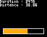
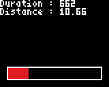
By default we fill the gauge in green, if the distance is inferior to 35cm we switch to orange and eventually to red if it goes below 15cm. Of course you can adjust those values if you want to. Be mindful to adjust the distance padding in the loop() function of you do modify those.
And voilà, you survived another Gamebuino tutorial. Congratulations !