Here is the small program I wrote to implement the use of a basic joystick on the Gamebuino Meta. Feel free to reuse and modify this code as much as you want to implement your own functionnalities.
/*Code by Tom from Gamebuino
 * Version 1.0
 * 22 of april 2021
 *
 * Intended as a simple demonstration of hardware use on the Gamebuino Meta console
 * Feel free to reuse this code and implement your own functionnalities
 */

#include <Gamebuino-Meta.h>

//variable declaration for the stick axis values and switch value
int32_t i32_X_axis;
int32_t i32_Y_axis;
int32_t i32_click = 0;

//variables used to draw the stick position as a DOT
int32_t i32_x_dot;
int32_t i32_y_dot;


//define of the 2 analog pins for axis values and digital pin for switch
#define X_PIN A1
#define Y_PIN A2
#define SWITCH_PIN 7

//define the values used to draw a circle in which to show stick position as a DOT
#define CIRCLE_X gb.display.width()/2
#define CIRCLE_Y gb.display.height()/2 + 5
#define CIRCLE_RAD gb.display.height()/3

void setup() {
  // put your setup code here, to run once:
  gb.begin();

  //set the input mode of the switch pin to INPUT_PULLUP
  //using only the INPUT mode will make the value flicker constantly
  pinMode(SWITCH_PIN, INPUT_PULLUP);
}

void loop() {
  // put your main code here, to run repeatedly:
  while (!gb.update());

  // the logic function will handle the math needed for the program
  logic();

  //the draw function will handle the display of all the elements needed for the program
  draw();

}

void  logic(){
  //we read the values from the stick pins
  i32_X_axis = analogRead(X_PIN);
  i32_Y_axis = analogRead(Y_PIN);

  //we convert those values to coordinates within a circle to have a visual feedback with the DOT
  //we substract half the maximum value of the stick input
  //since the default position is roughly X = 512 and Y = 512 this allows for a default position of 0, 0 instead
  i32_x_dot = ((i32_X_axis - 512) * CIRCLE_RAD) / 1023;
  i32_y_dot = ((i32_Y_axis - 512) * CIRCLE_RAD) / 1023;

  //we read the switch pin value to determine wheter the switch is active or not
  //by default an idle switch reads as 1 and an active one reads as 0
  i32_click = digitalRead(SWITCH_PIN);
}

void  draw(){
  // the clear function is needed to reset the screen between each frame, otherwise frames would mix together and get messy
  gb.display.clear();

  //we display all the raw values we read from our input pins in order, which makes our setup easier to understand
  gb.display.print(" X axis = ");
  gb.display.print(i32_X_axis);
  gb.display.print("\n Y axis = ");
  gb.display.print(i32_Y_axis);
  gb.display.print("\n ");
  gb.display.print(i32_click);
  if(!digitalRead(SWITCH_PIN)){
     gb.display.print(" CLICK");
  }

  //we draw a static circle in which we add a dynamic red DOT to show the stick position in real time
  gb.display.drawCircle(CIRCLE_X, CIRCLE_Y, CIRCLE_RAD);
  gb.display.setColor(RED);
  gb.display.fillCircle(i32_x_dot + CIRCLE_X, i32_y_dot + CIRCLE_Y, 5);
}
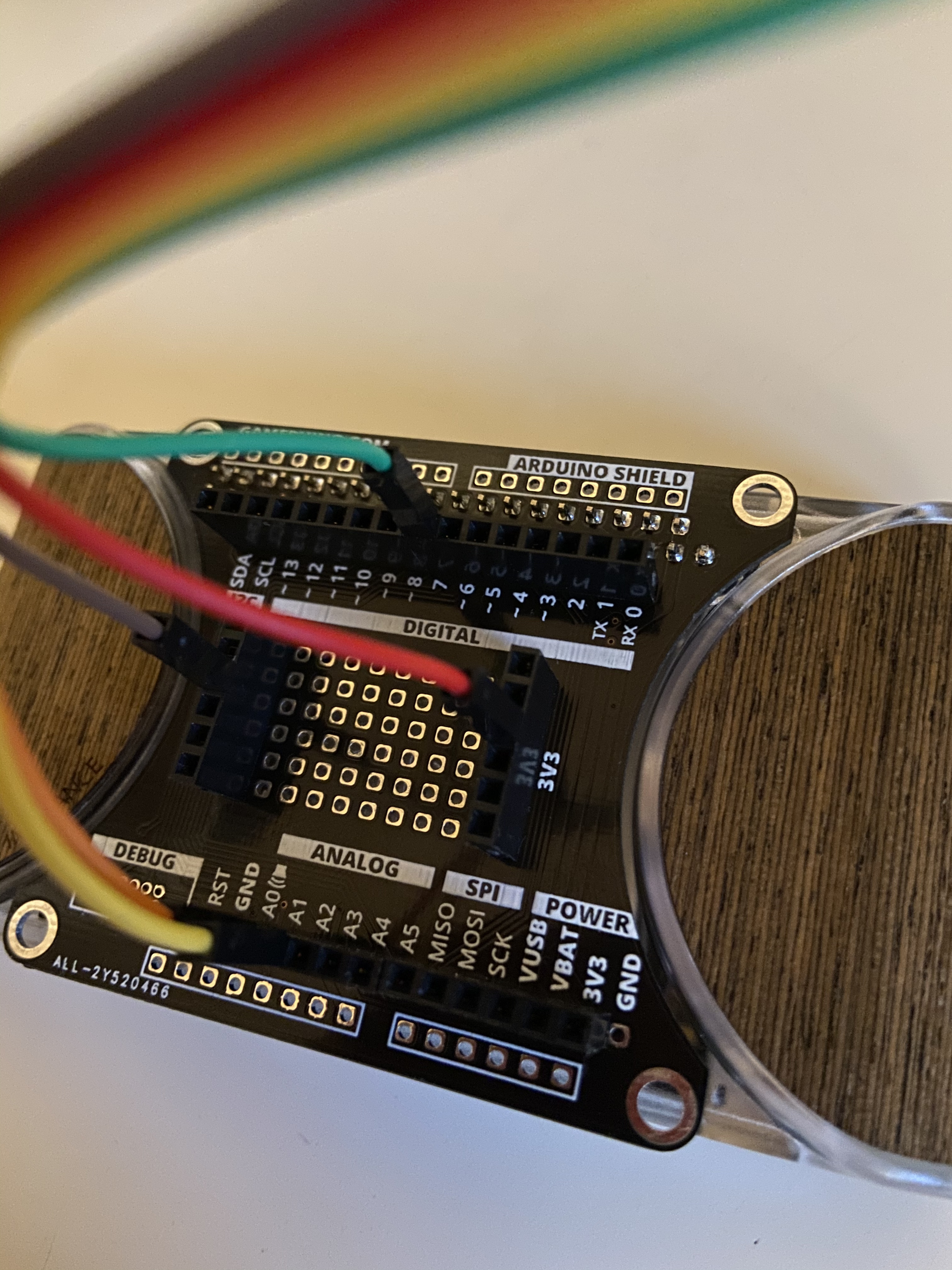
And here are a couple photos showing the wiring necessary to connect the stick to the console using the developper backpack expansion board for the Gamebuino Meta :
The X and Y outputs are plugged in the analog pins A1 and A2, the switch output is plugged to the digital pin 7, the power and ground wires are plugged in 3v3 and ground pins respectively.