In this tutorial we will see how to simply use the joystick from the accessory pack with CircuitPython.
Getting started : Tools requirement
This tutorial is made with Mu IDE for CircuitPython.
If you haven’t installed those yet please refer to the installation guide on our website.
Wiring :
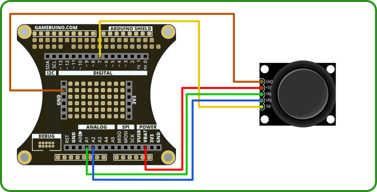
| Joystick | Backpack | Color | Description |
|---|---|---|---|
| GND | GND | BROWN | Ground |
| 5V | VBAT | RED | Power input |
| VRX | A1 | GREEN | X Axis |
| VRY | A2 | BLUE | Y Axis |
| SW | 7 | YELLOW | ISwitch |
Step 1 : Program’s Basis
Begin by opening Mu and creating a new file
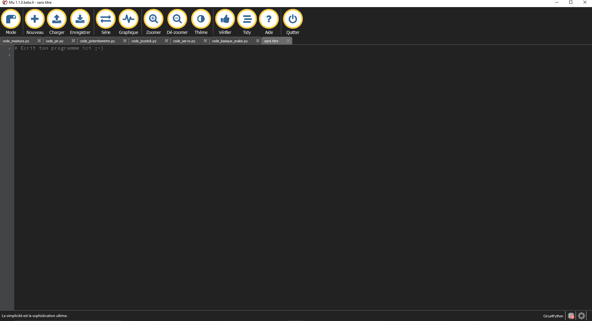
Copy the following code :
from gamebuino_meta import begin, waitForUpdate, display, buttons, color
import board
from analogio import AnalogIn

while True:
    waitForUpdate()
    display.clear()
This will import the Gamebuino libraries needed for the program to work, as well as a “board” and an “AnalogIn” libraries we will use to handle the joystick.
The part begining by “while True:” is our main loop, without it nothing would happen at all.
Step 2 : Configure the joystick
To be able to use the joystick we will need to read the values sent by the two pins corresponding to the X and Y axis. Since those are analog pins we will use the “AnalogIn” function to communicate with the stick.
For that purpose we define the attach pins of our two axis as follows :
x_pin = analogio.AnalogIn(board.A1)
y_pin = analogio.AnalogIn(board.A2)
We assign the A1 pin to the X axis and the A2 pin to the Y axis.
Steap 3 : Read and display
We can now proceed with the reading itself.
For that we use a small function called “read_input()” such as :
def read_input(pin):
    return pin.value
Calling this function and specifying which pin we want to read from will give us a value between 0 and 65536 (16 bits base)
To monitor the behavior of our setup we will display those values on screen.
Nothing complicated here, we just add a few calls the the print function in our main loop :
while True:
    waitForUpdate()
    display.clear()

    display.print("X = ")
    display.print(read_input(x_pin))
    display.print("\n")
    display.print("Y = ")
    display.print(read_input(y_pin))
A bit convoluted but since we don’t have access to a proper printf function we can’t do complex formating so we need to make do.
We will now create a specific function that will transform those values into a visual representation of our joystick.
This function will be called “draw_interface” and is declared as such :
def draw_interface():
It doesn"t do anything yet but we can already add a call to it in our main loop :
while True:
    waitForUpdate()
    display.clear()

    display.print("X = ")
    display.print(read_input(x_pin))
    display.print("\n")
    display.print("Y = ")
    display.print(read_input(y_pin))

    draw_interface()
We will represent the movement of our joystick in the form of a point moving inside a circle. So we will display those two elements :
def draw_interface():
    display.drawCircle(display.width()//2, display.height()//2, 20)

    dot_x = (read_input(x_pin) - 32768) * 20 // 65536
    dot_y = (read_input(y_pin) - 32768) * 20 // 65536

    display.setColor(color.RED)
    display.fillCircle(dot_x + display.width()//2, dot_y + display.height()//2, 5)
We start by drawing a circle with the function “drawCircle”, we place it at the center of the screen with a radius of 20 units.
We then calculate the coordinates of the point to display by reporting the values read from our two axis X and Y on this 20 units circle.
The we change the display color to red before using “fillCircle” to draw a red dot of 5 units radius that moves accordingly with the movement of our two axis.
You just went through another tutorial ! Now it’s your time to shine.